List the possible problems associated with air compressors which operate automatically.
Write the standing orders the Chief Engineer Officer should issue regarding the maintenance and safe and efficient operation of air compressors.
Outline any problems common to air receivers and machinery space/ship compressed air systems.
a.
Most of the problems with automatically operated air compressors lead to increased running hours. These include:
Leaking automatic drains - where the drain does not shut properly, due to dirt under the valve seat. Relief valves can also leak.
Unloaders not operating correctly.
Damaged or worn suction and discharge valves.
Dirty air filter
Leaks in compressed air system esp. auxiliary supplies to deck.
The increase in running hours may be gradual, and therefore go unnoticed. For this reason the running hours should be logged on a daily basis and any upward trend investigated and rectified. When possible the time taken to fill the air receiver should be tested and recorded.
Automatic drains not operating at all due to being choked with dirt can lead to a carry over of water/oil to the receiver. This can lead to an increase in corrosion, and a build up of oil film on the internal surfaces of the lines.
If a planned maintenance scheme is not in place or not applied effectively, then there is a chance that inefficiency of the air compressor due to the above or because of excessive wear will not be noticed until too late; i.e. when manoeuvering and the compressors cannot keep up with demand.
b.
Each Watch
Check oil level in sump; record amount used to top up. Do not overfill. Excessive consumption to be investigated. Any increase in crankcase pressure to be reported to 2/E to investigate and rectify
Drain air receiver of water .
Ensure that auxiliary air (esp. air to deck) is shut off when not in use.
Daily:
Record Running Hours
Check all automatic drains and unloader for correct operation.
Weekly:
check operation of relief valves fitted to intercooler, aftercooler, HP and LP stages by operating manually.
Planned Maintenance.
To be carried out as per instructions. Air filter to be changed every 500 hrs. Compressor valves to be removed for inspection and overhaul every 1000 hrs. Do not reverse compressor valve plates; there is a danger of them failing due to fatigue cracking. Every 2000 hours all automatic drains to be stripped, cleaned, checked and re-assembled. Relief valves fitted to LP, HP, intercooler and after cooler to be stripped, cleaned, overhauled and set at correct lifting pressures. Every 4000 hours: Major overhaul to be carried out as per manufacturers instructions.
c.
Corrosion is a problem common to receivers and systems. Water carry over in the air can lead to general corrosion and pitting. The air receiver is internally coated with a clear varnish to protect against this attack. Main air start lines are subject to survey, but should be regularly examined for corrosion/wastage. Oxidised lubricating oil carried over in the air can also cause corrosion. Air start pilot valves can corrode and jam preventing the engine starting. Corrosion in the main air start valve can cause the valve to stick in the open position, which is a potentially dangerous situation - possibility of an air start line explosion if there is oil present. For this reason and because of the aforementioned corrosive properties of oxidised oil, lub oil carry over must be kept to a minimum and every effort made to remove water from the system.
Tornado Click-AD
Thursday, April 22, 2010
Monday, April 12, 2010
Marine Engine -Question & Answer-Governor
Electrical power is provided from alternators driven by auxiliary diesel engines.
Using a sketch to illustrate your answer, describe a suitable governor.
Give an account of the governor action to increase the power delivered by the engine in response to a large electrical load increase while also restoring and maintaining the correct frequency.
Explain each of the following:
i) the necessity for droop;
ii) how droop is effected.
a.
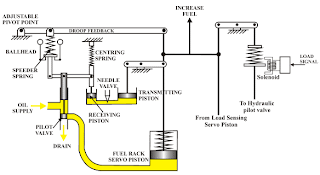
The sketch shows the principle of a hydraulic governor with feedback designed to return the engine to the set speed after a load change (isochronous).
A rotating ballhead driven from the engine and therefore proportional to engine speed operates a pilot valve to supply or drain oil from the underside of a fuel rack servo piston which is linked to the fuel rack. The movement of the ballhead is opposed by an adjustable speeder spring.
A floating link between the pilot valve, receiving piston and ballhead assembly means that for equilibrium with the pilot valve shut, the ballhead weights must always be in the same position (i.e. the engine must always be running at the same speed).
The governor also incorporates a load sensing arrangement for fast response in the event of a large change in electrical load
Provision is made for adjustable droop feedback which alters the compression on the speeder spring.
b.
Due to flywheel effect, and the response time of the hydraulic governor (viscosity of oil, friction) there will be a delay between the increase in load and the governor responding to the drop in speed. However the load sensing side of the governor will give a greater control of the speed with higher sensitivity and little droop.
When the load increases, the load sensing side of the governor will increase the fuel racks before the engine slows down. The speed sensing side of the governor fine tunes any small deviation in the speed of the engine.
The speed sensing side works as described below:
With an increase in load the engine slows down, The balls move inwards and the control valve moves downwards allowing oil to flow to the underside of the power piston, moving it upwards and increasing the fuel.
The transmitting piston moves downwards, increasing the pressure in the feedback system, moving the receiving piston upwards against the spring pressure, and shutting the pilot valve.
If there were no leakage in this feedback hydraulic system, then the result would be a permanent speed droop. However because oil is allowed to leak to a reservoir through a needle valve, the centering spring returns the receiving piston back to its original position, meaning the ballhead must be spinning at its original speed. Because the frequency is proportional to the engine speed, the frequency must be the same as it was before the load change.
c.
i)
Droop can be expressed as:
(no load speed - full load speed) / full load speed
When alternators are operated in parallel they must be fitted with governors which have a small amount of adjustable positive droop (i.e. the engine slows down slightly as the load is increased) so that they can load share equally.
If the governors were purely isochronous, then when trying to load share, the faster running machine would tend to take all the load.
ii)
With reference to the sketch in part (a) a linkage connected to the output of the governor moves about an adjustable pivot. As the output moves to put more fuel on the engine as a result of a load increase, the droop linkage reduces the compression of the speeder spring, thus reducing the speed of the engine.
Friday, April 9, 2010
Marine Engine Question & Answer-Crankcase Explosion
Outline the probable events leading to an explosion, for an engine where a hotspot has developed in the crankcase.
Compare the methods of operation and the performance characteristics of BOTH obscuration and light scatter type oil mist detectors.
Explain how the severity of a crankcase explosion may be limited.
Explain why stopping rather than slowing down in the event of an overheated crankshaft bearing is preferable.
a.
For an explosion to occur there must be oxygen, fuel, and a source of ignition. The oxygen will be present in the air in the crankcase, The lubricating oil is the fuel, and the source of ignition is usually an overheated bearing (although it can also be anywhere two metals are rubbing together, or blowby on a trunk piston engine)
The mixture of oil and air must be in a ratio that is within the range of inflammability; the splashing of the lubricating oil inside the crankcase breaks it up into droplets or globules of widely varying size distributed in varying density throughout the crank chamber. The overall mixture strength is usually very weak and will not support combustion. However, if a hot spot exists, some oil will come into contact with it and will be vaporised, circulate to cooler parts of the crankcase and there condense to form a white mist of finely divided oil particles well mixed with air. This mist is combustible within certain concentrations. If the mist should now circulate back to the hot spot in such concentrations, it will be ignited and a primary or minor crankcase explosion will occur. This explosion causes a flame front and pressure wave to accelerate through the crankcase, vaporising further oil droplets in its path.
The pressure shockwave may build up sufficiently by the time it reaches the crankcase casing to rupture crankcase doors or panels, unless otherwise relieved. If the pressure wave reaches an opening through which it can escape to the atmosphere the pressure pulse is immediately followed by a suction pulse of lower magnitude but greater duration. This suction pulse can be responsible for drawing in a charge of fresh air to take the place of that which has been burned by the initial explosion. A secondary explosion or major explosion of such intensity as to cause widespread damage then follows.
b.
Light Scatter
Obscuration
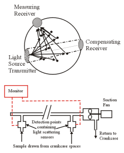
In the light scatter type of crankcase oil mist detector individual sensors are placed at each monitoring point - each crank throw space and chain case (where applicable). A suction fan draws the sample through each detector. Light is transmitted at one end of the head where the sample flows through. Directly opposite the transmitter is a compensating receiver. This adjusts the light intensity by feeding back a signal to the transmitter. A measurement sensor picks up the scattered light produced by the oil mist particles. The result is transmitted as an analogue signal back to the monitor twice per second. The monitor compares this signal against a set point, and an average of the other readings. When the scattered light picked up by the sensor reaches a pre determined point an alarm condition will be reached.
Advantages claimed for this system are:
Sampling points fitted close to crankcase - no long runs of piping.
Continuous parallel sampling - no high maintenance selector valves.
Fast response time - may save the engine from bearing failure.
The obscuration type of detector consists of two parallel tubes of equal size, each having a photoelectric cell at one end which generates an electric current directly proportional to the intensity of the light falling on its surface. Lenses are fitted to seal the ends of each tube but allow light to pass. Two identical beams of light from a common lamp are reflected by mirrors to pass along the tubes onto the cells which are then in electrical balance.
The samples drawn from the crankcase are drawn in turn along the measuring tube by means of a selector valve. If a concentration of oil mist is present in the sample, the light will be obscured in the measuring tube: electrical balance between the two cells will be disturbed and an alarm will be operated.
The model shown measures total mist concentration with respect to clean air. An alternative model draws samples through both reference and measuring tubes. A mixture from all cylinder crankcases is passed through the reference tube while comparison is made with samples from each cylinder crankcase and also from the atmosphere. In this manner a general sample of all cylinders is compared with the normal atmosphere and each individual sample is also compared against the average.
This type of detector has the advantage of simplicity of operation. The disadvantages are that comparatively long runs of pipework from sampling points to detector are required, only one sample point is measured at a time, and regular maintenance is required if false alarms are to be avoided.
c.
The severity of the crankcase explosion can be limited by reducing the pressure shockwave travelling through the crankcase; This can be achieved by subdivision of crankcase which will inhibit the build up of high velocities and pressures of flame propagation through the crankcase from a primary explosion. The pressure build up must be relieved without allowing air to be drawn back into the crankcase thus preventing a secondary explosion. To do this, the crankcase is fitted with explosion doors, which are in effect spring loaded, low inertia non return valves of sufficient size to relieve any build up of pressure (115 cm2 per cubic metre of crankcase volume) The doors are fitted with a gauze flame trap, wetted by crankcase oil, and a deflector on the exterior to prevent harm to personnel.
d.
An overheated bearing will be the cause of the generation of the vaporised oil and the source of ignition. If bearing temperature probes are fitted it may be possible to prevent the vaporisation of the oil, and running of the bearing white metal by stopping the engine before the bearing has become too hot; However the main worry besides the formation of the oil vapour and the possible danger of explosion is the damage to the crankshaft by scoring or overheating which can mean the scrapping of the crankshaft. In the case of a high oil mist alarm, the cause of which may well be an overheated bearing, or a bearing high temperature alarm, it is best to stop the engine immediately. However safe navigation of the vessel, may cause the Master/OOW to overide this, in which case reducing the load to 50% may well limit the damage caused until the engine can be safely stopped.
Labels:
CC Explosion Detector,
Crankcase Explosion,
OMD
Wednesday, April 7, 2010
Marine Engine-Question & answer-Crosshead
Sketch a large crosshead, showing the piston rod, connecting rod and slipper connections.
Describe how top end bearings and slippers are supplied with lubricating oil.
State what factors govern load bearing capacity of top end bearings.
a.
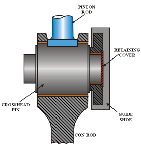
The sketch shows a partial section through the crosshead on a modern large slow speed engine.
The piston rod is bolted to the crosshead pin which reciprocates in the crankcase. The connecting rod swings about the crosshead pin and transfers the downward thrust to the crankshaft converting it to rotary motion. The side thrust is transferred into the engine by the guide shoes which reciprocate in the crosshead guides which are bolted to the A frames
The top end of the connecting rod is forged to form the housing for the continuous bearing. This combined with a large pin diameter gives the maximum surface area thus reducing the loading on the bearing to a minimum.
The top half of the bearing is located in a bearing cap which incorporates a slot to allow the piston rod foot to be bolted to the top of the crosshead pin.
The large diameter finely finished hardened pin is reduced at each end to form journals on which the guide shoes are located. The guide shoes which run in the crosshead guides are free to rotate a limited amount to allow for slight misalignment. To allow this rotation, the locating bores of the guide shoes are lined with a white metal bearing. A retaining cover holds the shoe in place on the journal.
b.
Oil is supplied to the crosshead via a telescopic (MAN B&W) or a swinging arm link (Sulzer). The oil supplies the crosshead bearing, the guide slippers, oil for piston cooling and bottom end bearing. On the sulzer engine, the oil is boosted in pressure to about 12bar.
c.
The crosshead on a slow speed 2 stroke is a difficult bearing to lubricate effectively. The load is continually downward and because the con rod swings about the pin, changing direction each stroke, true hydrodynamic lubrication cannot take place. Instead the lubrication starts as boundary, and as the rubbing speed increases, a hydrodynamic film is built up. As the rubbing speed decreases the lubrication becomes boundary once again.
Modern top end or crosshead bearings are of a tin aluminium alloy which has a higher load bearing capacity than a tin antimony babbit metal. To increase the load bearing capacity, the pin diameter is as large as possible to increase the rubbing speed, and the continuous lower bearing increases the bearing area over that of the older forked type crosshead.
Tuesday, April 6, 2010
Marine Engine-question & Answer-Viscotherm
Describe with the aid of a sketch, the main engine ancillary equipment for automatic monitoring and regulation of fuel viscosity.
Explain the operation of equipment described in Q.(a)
Discuss the single fuel concept.
a.
The sketch shows the system for automatic monitoring and regulation of fuel viscosity. The main components of the system are:
Fuel Oil Heater: Uses steam as the heating medium although electrical models are in existence. Tubular design.
Viscotherm: Basically consists of a small gear pump that pumps some of the oil through a capillary tube. The pressure in the capillary increases as the viscosity of the oil increases.
DP Transmitter: Converts and transmits the differential pressure measured at the viscotherm to an air signal.
P+I Controller: Amplifies the air signal from the DP cell and feeds it to the steam control valve via the Hand/Auto station.
Hand/Auto Station: Can be used to directly control the air signal to the steam control valve.
Control Valve: Controls the amount of steam flowing to the heater.
b.
Consider a rise in the viscosity of the fuel being delivered to the engine. The pressure in the capillary of the viscotherm increases, leading to a rise in the differential pressure between the beginning and end of the capillary. This increased differential pressure is converted into an air signal which is proportional to the rise in differential pressure. The amplified output signal is fed via a hand/auto station to a control valve which opens the steam control valve. The valve position may be fed back to the transmitter to provide more accurate control of the valve and prevent hunting. The viscotherm is fitted with a bypass, and the steam control valve can be operated by hand from the hand/auto station.
c.
When engines started burning the lower grades of residual fuel, the systems incorporated diesel change over valves, because prior to manoeuvring (i.e. stand by arrival, departure, canal and river transits etc.), the engine was changed over to run on the distillate marine diesel oil which required no heating. Older engine fuel pump and injector systems did not incorporate recirculation valves, and so if the engine was at standstill any heated fuel in the long HP fuel pipes would cool, and would not be at the correct viscosity for injection when the engine was restarted. This would lead to poor combustion, and associated pollution until the fuel at the correct viscosity reached the injectors. In extreme cases, the injectors would have to be bled before the engine could be started.
Modern 2 stroke injectors incorporate recirculation valves, so that there is no need to change over to MDO for manoeuvring purposes, as the oil at the injectors is always at the correct temperature to give it the correct viscosity. This represents a considerable saving to the ship operator as the difference in cost between residual and distillate fuel is considerable.
An exception to the above is when the engine is to be shut down for maintenance to the injection pumps. MDO is often used for the last 30 minutes or so before shutdown, to avoid the mess made by heavy oil when opening up fuel pumps etc.
Marine Engine-Question & Answer-Purifier
a.Describe an automatic self sludging centrifuge suitable for dealing with fuel of density up to 1010kg/m3 at 15ºC.
b.Explain how the centrifuge described in is able to remove water from a fuel which has a density that is higher than that of water and state any factors that may assist the operation.
As Chief Engineer, write out the start up procedure for the centrifuge described in for the benefit of your staff.
State how the problem of catalytic fines in fuel oil may be dealt with.
a.
As the density of the oil approaches that of water (above 991kg/m3 ) the hydraulic equilibrium in the bowl becomes unstable, and a gravity disc will no longer maintain a water seal.
To overcome this problem, Alpha Laval has developed the Alcap separator, the principle of which is illustrated.
Oil is fed into the high speed rotating bowl which basically operates as a clarifier, but water and solids are separated and are thrown to the outside of the bowl by centrifugal force.
At regular intervals a sludge cycle will take place. Water is admitted into the bowl to soften the sludge and displace the oil in the bowl. When a transducer in the oil discharge line detects water the bowl is opened and the sludge and water discharged. The bowl opens and closes very rapidly and oil loss is minimal.
If the fuel contains water it will build up in the bowl and start to be discharged with the clean oil. The transducer in the discharge line will detect this and if this occurs after the minimum sludge cycle time, a sludge cycle will be initiated; if the water is detected before the minimum sludge cycle time, then water discharge valve will open.
b.
Density of fuel is quoted at 15ºC. This density will fall as the fuel is heated up. The density of water, although it does change a very small amount, stays fairly constant at 1000kg/m3 . By heating the oil to as high a temperature as possible (90 - 98ºC) the relative density is reduced to below that of water, allowing the water to be thrown to the outside of the bowl.
Other factors that assist separation are:
Viscosity of the oil: The lower the viscosity the lower the drag force on sludge particles. Viscosity of a fuel is reduced by heating.
Throughput: Should be as slow as possible to maintain fuel demand.
Interface: If the oil/water interface is within the disc stack separator efficiency is reduced as oil cannot flow along the full surface of the disc.
c.
Ensure purifier has been fully assembled, that the bowl cover locking dogs are in position, and the brake is off.
The purifier pump suction should be closed, the pump discharge valve open to the heaters, and the recirc valve open back to the purifier suction. The discharge from the purifier should be open to the settling tank.
The feed regulating valve to the purifier should be set to zero.
Start the purifier watching the ammeter which should fallback as the purifier speed increases. Ensure the purifier does not vibrate. In case of vibration or excessive current shut down immediately and investigate.
Open the fuel suction from the settling tank to the purifier pump.
Warm through and open heating steam to and from heaters. Ensure heater control set to 95ºC.
Continue to recirc fuel until purification temperature is reached.
Open operating water and set bowl operating water to close.
Open feed regulator to purifier and shut recirc valve. Set purifier oil feed to minimum.
Ensure sludge cycle is set to x hours.
Change discharge from settling to service tank, and adjust feed rate to match engine consumption.
d.
Catalytic fines comprise of small particles of silicon and aluminium carried over from the refining process. They cause abrasive wear in fuel pumps, injectors, liners and piston rings.
They are difficult to remove because they are often hollow which gives them a relative density close to that of the fuel. Experience has shown that by keeping the total contamination below 80mg/kg, efficient centrifuging could keep the fines down below a level when abrasive wear takes place. This means keeping the purification temp as high as possible and the throughput as low as possible.
Marine Engine -Question and answer-Injector
With reference to fuel injectors:
a.sketch a fuel injector, labelling the parts which influence atomisation of the fuel and the spray pattern;
b.explain how a fuel injector may deteriorate in service resulting in poor atomisation;
c.explain how defective fuel atomisation may be detected during engine service.
a.
b.
Repeated operation of the fuel injector will lead to weakening of the spring. this will allow the injector to open early, and at a lower pressure correct atomisation and penetration into the combustion space will not occur as there is not sufficient pressure energy for conversion in the atomisation holes. Repeated operation will lead to erosion and enlarging of the atomisation holes, accelerated by using fuel contaminated with water or catalytic fines. The holes will be of the wrong shape and size to allow efficient atomisation. Wear of the needle and nozzle seating will allow dribbling to take place, again interfering with the pressure rise required to allow correct atomisation to take place.
c.
The first signs of defective atomisation may be noticing a drop in power from the engine. The colour of the exhaust from the funnel will darken indicating poor combustion. Because atomisation and penetration is not correct and the fuel droplets larger than they should be, afterburning may occur causing higher than normal exhaust temperatures. If allowed to continue over a period of time, fouling of the turbocharger will occur, leading to a drop off in performance. If defective fuel injection is suspected, then an out of phase card can be used to show faults with the fuel injection. If confirmed, the injector should be changed as soon as possible.
Marine Engine-Question and answer
1.(a)Explain why bottom end bolts are prone to failure under normal conditions.
(b)Describe how bottom end bolt failure is either aggravated or inhibited
during maintenance.
(c)Describe with the aid of sketch, the features incorporated into bolt design
to inhibit failure.
(a)
On a 4 stroke engine, the bolts and their nuts are subject to tensile stress when tightened and additional varying tensile stress during operation. The total stress level is high and varies with time, giving rise to the risk of fatigue. The connecting rod is in compression during the compression and power strokes, but due to the inertia forces in the running gear when the piston changes direction between the exhaust and inlet strokes, the connecting rod is put into tension. This increases the tension in the bottom end bolts, leading to cyclic stressing.
(b)
Over-tensioning of bolts should be avoided as this increases the stress level. If bolts are damaged during maintenance, stress raisers will result, thereby increasing the risk of fatigue.
When inspecting the bolt check for:
Corrosion – acid attack from LO.
Elongation.
Mechanical damage – dents, burrs, etc.
Fretting on landing faces
Thread condition
Cracks – NDT, dye penetrants.
Only tighten to manufacturers recommendations; hydraulic jacks, stretch measurement, or using jig and feeler gauges
In order to minimise the risk of fatigue failure, bottom end bolts should be replaced if the bolt elongation has reached a maximum (go – no go gauge) or after about 15,000 running hours.
(c)
Subscribe to:
Posts (Atom)